You may
Note
You may translate POINT’s, LINE elements
and 3DFACE’s. POINT’s are converted into
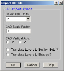
Select the units you used in the CAD model from which you produced the DXF file. The supported DXF units are none, inches, feet, mm, cm, and meters.
Enter the scale factor that will cause the DXF file to be scaled up or down to full scale. For instance, if you had created a scaled model in AutoCAD at a scale of 1/4"=12", then the appropriate scale factor to produce a full size RISA-2D model would be 48. The default is 1.0.
Although it is not specifically noted in the AutoCAD documentation, the implied default vertical axis is the positive Z-axis of the current User Coordinate System.
The default vertical axis in RISA is usually the positive Y-axis and may be specified in the Model Settingsunder the Axis Tab. When you import your model from a DXF file, you can have the program automatically rotate your geometry so that the Y axis is now the vertical axis for your RISA model.
This is a Yes/No check box. If you check the box “Yes”, the program will translate the DXF file's layer names into RISA Section Sets Labels. The program requires that you add a prefix to each Layer Name to designate what type of material that section set is defined for. The prefixes are as follows:
| Material Type | Layer Prefix |
|---|---|
|
Cold Formed Steel |
CF_ |
|
Concrete |
CN_ |
|
Hot Rolled Steel |
HR_ |
|
General Materials |
GN_ |
|
Wood |
WD_ |
For example, let’s say you have designed a structure with Hot Rolled steel section sets that you want to call "Column"and " Girder", as well as a Wood section set called "Joist". If you do not prefix your section sets then they will all be imported as General Material section sets. To have them imported into the proper Material type the column layer would have to be named "HR_Column", the girder a layer "HR_Girder", and the joists layer "WD_Joist".
This is a Yes/No choice. If you choose “Yes”, the program will take members and assign them to a shape based on their shape label. If there is not a database shape that corresponds to the DXF Layer Name, then these member will be assigned a general RE4x4 shape or a BAR2.
Note
Only the
Type the name of
the layer for the
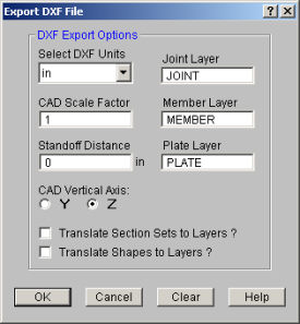
Type the name of the layer for the line entities. If you don’t enter anything, the default layer name will be “MODEL”. Note that this entry will be ignored if you select the option below to translate section set database shape names into layer names.
Type the name of the layer for the plate elements, which will be represented as 3DFACE entities. If you don’t enter anything, the default layer name will be “MODEL”.
Select the units you desire the CAD model to be created in. The options for the DXF units are none, inches, feet, mm, cm, and meters.
Enter the scale factor that will cause the full scale RISA model to be scaled up or down to the desired drawing scale. For example, if you created a full scale model that you wanted scaled down to 1/4"=12", the factor would be 0.020833, which is (.25/12).
Enter the distance you wish to have
the line entities “stand off” from the
Note that if you
create a DXF file with a non-zero standoff distance, it will be difficult
to use the file for model geometry if you read the file back into RISA.
(If you read such a file back in, you will end up with multiple
Although it is not specifically noted in the AutoCAD documentation, the implied default vertical axis is the positive Z-axis of the current User Coordinate System.
The default vertical axis in RISA is usually the positive Y-axis and may be specified on the Model Settings. When you export your model to a DXF file, you can have the program automatically rotate your geometry to match the vertical axis of your CAD program.
This is a Yes/No check box. If you check the box “Yes”, the program will translate Section Set Labels to layer names. Layers will be created in the DXF file corresponding to the section set labels in the RISA model. A “Yes” choice here overrides any layer name entered for the member layer.
The program will add a prefix to each section set layer to designate what type of material that section is. The prefixes are as follows:
| Material Type | Layer Prefix |
|---|---|
| Cold Formed Steel | CF_ |
| Concrete | CN_ |
| Hot Rolled Steel | HR_ |
| General Materials |
GN_ |
| Wood | WD_ |
For example, let’s say you have designed a structure with Hot Rolled steel section sets called "Column"and " Girder", as well as a Wood section set called "Joist". If you type in a member layer name such as "STEEL" then all members, regardless of size, will appear on a layer named "STEEL". However, if you choose “Yes” for the translate section sets to layers option, then all the member that are assigned to the Column section set will appear on a layer named "HR_Column", the girders on a layer named "HR_Girder", and the joists on a layer called "WD_Joist".
This is a Yes/No choice. If you choose “Yes”, the program will take members and assign them to a layer which uses their shape label as the layer name. Layers will be created in the DXF file corresponding to the shape labels in the RISA model. A “Yes” choice here overrides any layer name entered for the member layer.
Note:
It's always a good idea to do a Model Merge on any model created from a DXF file! In the process of creating a wire frame model in your CAD software, certain events may take place that cause end-points of LINE elements that were once matched to become mismatched by very small amounts. This most often happens as a result the following:
Model Merge combines
You can also deal with several other possible problems
by performing a Model Merge. This feature will also deal
with intermediate
Different CAD packages handle ordering of geometric data in their DXF files in two basic ways.
Entities are written out into the DXF file based on the order in which they were created within the CAD program itself regardless of the order in which they were selected at the time the DXF file was made. Different operations such as copying, mirroring, arraying, etc. can produce unexpected results and it therefore becomes necessary to consult your CAD program documentation to understand how it stores and orders the geometry that you create via these various operations.
Entities are written out into the DXF file based on the order in which they were selected at the time the DXF file was made. AutoCAD is such a program. In order to control the ordering of the LINE entities, you must select the "Entities" option under the DXFOUT command and then select the lines in the order that you want them to appear in the RISA model.
Note
The specific DXF file that you may read and write is the ASCII Drawing eXchange Files (DXF) file. Please note that AutoCAD has several different forms of DXF files available. ASCII is the default form and is the only form currently supported. The DXF read/write feature was written based on the DXF documentation for AutoCAD release 14. The feature has been tested with AutoCAD Versions 13 and 14.
The following is a short excerpt of the AutoCAD ASCII DXF format. This information is provided to help you debug any problems you may be having with DXF files that you are trying to read. For more complete information, consult your CAD documentation.
A DXF file is composed of sections of data. Each section of data is composed of records. Each record is stored on it’s own line. Each particular item is stored as two records, the first record is a group code and the second record is the data or a keyword. RISA only reads the ENTITIES section.
Each 2 record item start with an integer group code. RISA recognizes the following group codes:
| Group Code | Description |
|---|---|
|
0 |
Identifies the following overall keywords: SECTION, ENDSEC, and EOF. Within the ENTITIES section it also identifies POINT, LINE, and 3DFACE. |
|
2 |
Identifies a section name (I.e., ENTITIES) |
|
8 |
Identifies a layer name. |
|
10, 11, 12, 13 |
Identifies the X coordinate of the 1st, 2nd, 3rd and 4th points of an item. |
|
20, 21, 22, 23 |
Identifies the Y coordinate of the 1st, 2nd, 3rd and 4th points of an item. |
|
30, 31, 32, 33 |
Identifies the Z coordinate of the 1st, 2nd, 3rd and 4th points of an item. |
Each DXF file must start with the first record as the group code “0”. The 2nd record must be the keyword “SECTION”. Each DXF file must have the 2nd to last record as the group code “0". The last record must be the keyword “EOF”.
The ENTITIES section will be identified by a group code of “0”, followed in the next record by the keyword “SECTION”. The next record will be the group code 2, followed in the next record by the keyword “ENTITIES”.
The POINT format is started by a group code of “0” followed by the keyword “POINT”. The layer name for the POINT will start with a group code record of 8, followed by a record with the actual layer name.
The coordinates for the point will be started by the 10, 20, and 30 group codes respectively for the X, Y, and Z coordinates. Other group codes and data may be present within the POINT data but these will be ignored.
The LINE format is started by a group code of “0” followed by the keyword “LINE”. The layer name for the LINE will start with a group code record of 8, followed by a record with the actual layer name.
The coordinates for the first point will be started by the 10, 20, and 30 group codes respectively for the X, Y, and Z coordinates. The coordinates for the second point will be started by the 11, 21, and 31 group codes respectively for the X, Y, and Z coordinates. Other group codes and data may be present within the LINE data but these will be ignored by RISA-2D.
The 3DFACE format is started by a group code of “0” followed by the keyword “3DFACE”. The layer name for the 3DFACE will start with a group code record of 8, followed by a record with the actual layer name.
The X, Y, and Z coordinates for the 1st through 4th points will be started by the 10, 20, and 30 through 14, 24, and 34 group codes respectively. Other group codes and data may be present within the 3DFACE data but these will be ignored.
The only valid characters in an AutoCAD layer name are the letters A to Z, the numbers 0 to 9, and the three following characters: the dollar sign “$”, the underscore “_”, and the dash “-”.